Welcome to the first episode of “Basic Projects”, a beginner-friendly series where we build simple and practical PLC programs using Siemens hardware and TIA Portal.
Today, we’re starting with a true classic: 👉 Blinking an LED
This guide is perfect for beginners who want to understand the basics of output control and see how the same logic can be written in different ways.
🧰 What You’ll Need :
- TIA Portal installed ✅
- A Siemens S7-1200 PLC (e.g. CPU 1215C) ✅
- A connected LED or a digital output (Q0.0) ✅
- Basic wiring + 24V power supply ✅
🛠️ Step 1: Project Setup in TIA Portal
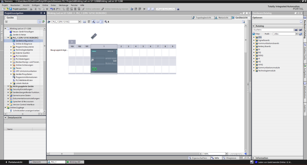
- Open TIA Portal and create a new project
- Add your PLC hardware (we’re using 1215C DC/DC/DC)
⚙️ Step 2: Enable Clock Memory (Taktmerkerbytes)
- Go to “Device Configuration”
- In the project tree on the left side, expand your PLC’s folder
- Double-click “Device Configuration” to open the hardware view
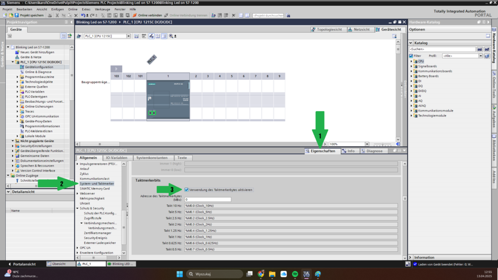
- Open CPU Properties
- In the hardware view, click on your CPU module (e.g. CPU 1215C DC/DC/DC)
- On the right panel, you’ll now see the “Properties” tab
- Click it to open all editable settings
- Navigate to “System and Clock Memory”
- In the Properties tab, scroll down the left panel
- Find and click on “System and Clock Memory”
(In German: “System- und Taktmerker”)
Check the box “Enable Clock Memory” TIA Portal will automatically assign symbolic names to the clock memory bits (like M10.0 to M10.7) once you enable the Clock Memory (Taktmerkerbytes) in the CPU settings — you don't need to declare them manually.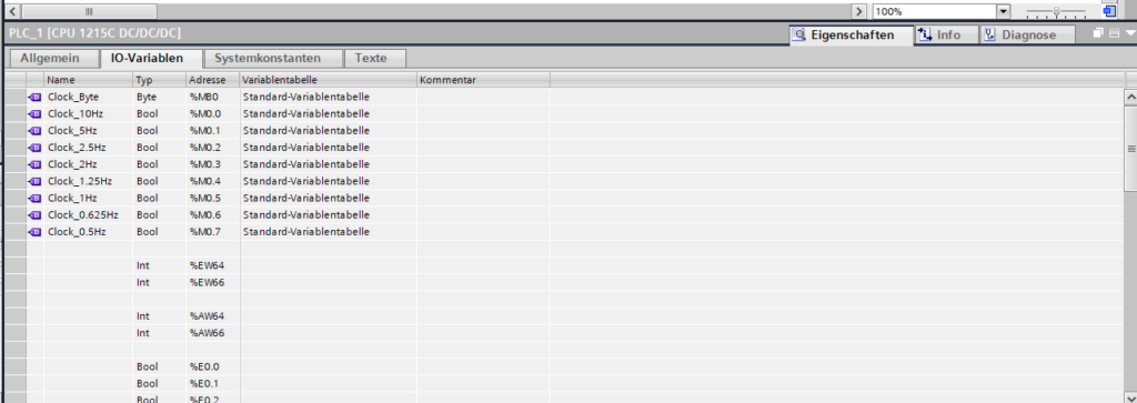
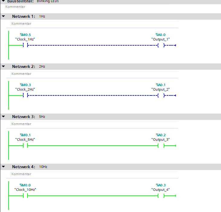
🪜 KOP (Ladder Logic)
- Create a single rung:
- Use a Normally Open (NO) contact for your clock memory bit (e.g.
M10.5), - connect it to a coil that controls your output (e.g.
Q0.0).
- Use a Normally Open (NO) contact for your clock memory bit (e.g.
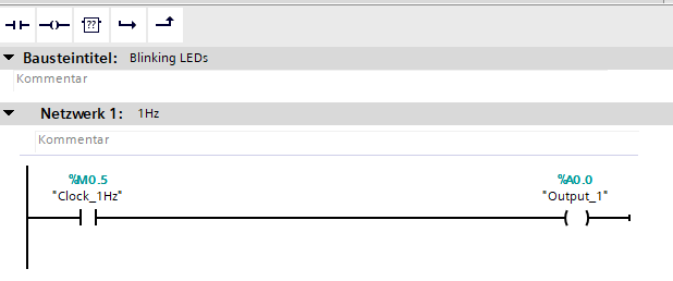
🖼️ Ladder logic is great for electricians or anyone with relay logic experience.
📐 FUP (Function Block Diagram)
- This version is visually similar:
- Use an Examine Bit block for M10.5
- Wire it to an Output Coil for Q0.0
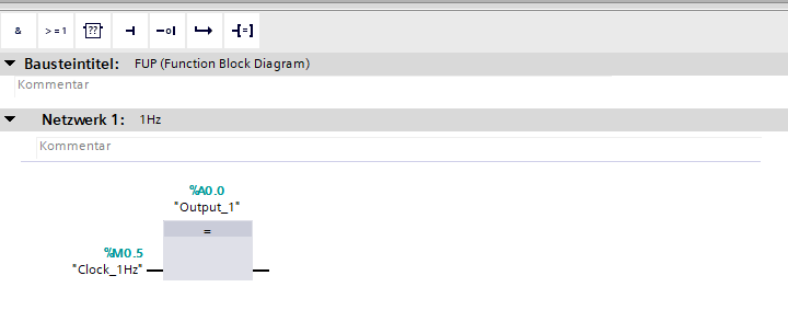
🖼️ FUP is clean, graphical, and perfect for visual learners.
🧾 SCL (Structured Text)
"Output_1" := "Clock_1Hz";📌 This line simply assigns the state of the 1 Hz clock memory bit (M10.7) to the digital output Output_1
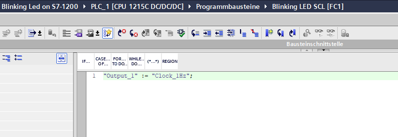
That’s it! The simplest and most readable way if you’re into code.
🔄 Step 3: Compile, Download & Run
- Hit Compile

- Connect to your PLC

- Download the program

- Switch your PLC to RUN mode

🎉 You should now see your LED (or Q0.0) blinking once per second. (1Hz)
✅ Wrap-Up
And that’s it — our first PLC project is complete!
- Whether you used:
- KOP for relay-style logic
- FUP for functional clarity
- or SCL for clean, code-like simplicity…
- …the output is the same: a blinking LED.
Very nicely presented knowledge👌
Bardzo fajnie przygotowany poradnik! Wszystko opisane jasno i zrozumiale — krok po kroku, bez kombinowania. Bez problemu udało mi się uruchomić migającą diodę na sterowniku m. Super sprawa dla tych, którzy zaczynają przygodę z PLC albo chcą sobie przypomnieć podstawy. Czekam na kolejne wpisy!
Good job!
Keep it up 🔥