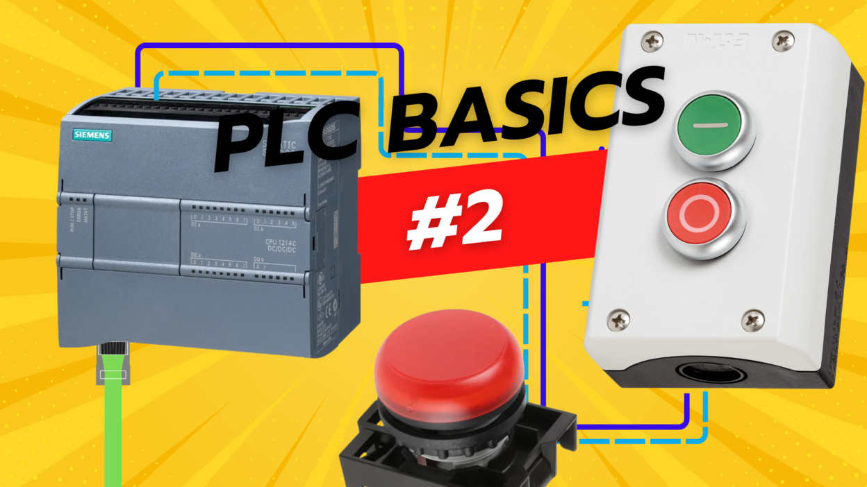
Controlling an LED using a button is one of the simplest and most important tasks when learning how to work with a PLC. It introduces you to the concept of digital inputs and outputs — the foundation of automation. In this blog post, we’ll walk you through how to wire and program a button to control an LED using a Siemens S7-1200 PLC in TIA Portal.
What You’ll Need 🧰
- Siemens S7-1200 CPU (e.g., 1212C or 1215C)
- 24V DC Pushbutton (NO – normally open) 🔘
- 24V DC LED indicator (or a 24V pilot lamp) 💡
- 24V DC power supply ⚡
- TIA Portal (V16 or higher) 💻
Basic Wiring 🔌
- Button wiring (Digital Input):
- One side of the button to +24VDC.
- The other side to PLC Digital Input, e.g., I0.0.
- The input module internally pulls to GND, so you don’t need a pull-down resistor.
- LED wiring (Digital Output):
- One side of the LED to PLC Digital Output, e.g., Q0.0.
- The other side to 0V (GND).
- If your LED doesn’t have a built-in resistor, add one (1kΩ–2.2kΩ is safe for 24V).
TIA Portal – Step-by-Step Programming 🧑💻
- Create a new project and add your S7-1200 CPU.
- Configure I/O addresses:
- Input: I0.0 (button)
- Output: Q0.0 (LED)
- Open the Main OB1 (or create a new network).
- Add a normally open contact for the button:
- Name:
Button - Address:
%I0.0
- Name:
- Add a coil for the LED:
- Name:
LED - Address:
%Q0.0
- Name:
LADDER Example:
Network 1:
| %I0.0 (Button) | ——[ ]——+——( )—— %Q0.0 (LED)
What it does:
When the button is pressed (input I0.0 goes HIGH), the LED turns ON via output Q0.0. When the button is released, the LED turns OFF. Simple as that! 👍
Watch it in Action 🎬
This logic is real-time and momentary — it behaves like a normal light switch button. You press the button, and the LED lights up as long as you’re holding it.
Want the LED to stay on even after releasing the button? That’s called a latching function 🔁 and we’ll cover that in the next blog post!
Conclusion ✅
Understanding how digital inputs and outputs work is the starting point for every automation engineer. With this basic LED control using a button on a Siemens S7-1200 PLC, you’ve already stepped into the world of industrial control. 🚀
Next steps:
- Try adding a second button to turn the LED off (Set/Reset) ⏹️
- Add a delay using a TON (On-delay timer) ⏱️
- Explore HMI integration to control the LED from a screen 🖥️
If you found this helpful, consider subscribing or following for more Siemens PLC tutorials! 📘✨
Want me to turn this into a short social media post or make a matching wiring diagram?


